Improve Your Parts with Custom Injection Mold Design
A successful plastic injection mold requires collaboration between your organization and the injection molder. Based on their expertise and industry experience, they will help you develop and optimize the design of your custom mold, select the appropriate material, and ensure the injection molding process meets the required quality and regulatory standards.
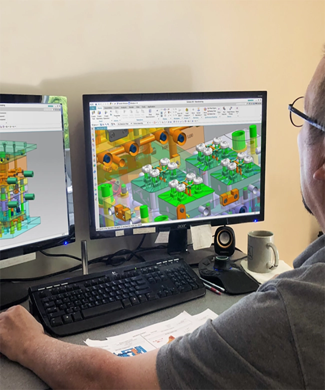
Already have an idea of your injection mold design? Get started today by contacting our engineering team.
Our mold design process is driven by precision engineering, manufacturability analysis, and long-term performance. From concept validation to final tool design, we focus on efficiency, durability, and cost optimization to ensure flawless injection molding results.
Do the cavitation number and layout match the Tooling Data Sheet (TDS)?
Is the mold layout design reasonable and manufacturable?
Does the shrinkage rate comply with the TDS?
Is there any “bad steel” condition in the design? If yes, are spare inserts considered?
Are all shut-off areas designed with a minimum 3° draft angle?
2. Machine & Mold Compatibility
Is the tie bar spacing sufficient for the mold size?
Is the maximum mold opening stroke sufficient?
Do the mold clamping method and clamping plate size meet customer requirements?
Can the mold run in fully automatic mode?
3. Mold Base & Standard Components
Do all standard components comply with the Tooling Data Sheet?
Are catalog numbers specified for all standard components?
Does the drawing include a complete and accurate BOM?
Is there zero clearance between the sprue bush, A-plate, and cavity insert?
Are the locating ring diameter and sprue radius compliant with the TDS?
4. Lifting, Handling & Safety
Are the eyebolt hole quantity, size, and quality sufficient and per customer requirements?
Are eyebolt holes designed when mold weight exceeds 25 kg?
Is the safety strap designed according to customer or SSL standards?
Is a rest hole provided where required?
5. Guiding & Alignment
Do guide pins engage at least 15 mm into guide bushings when the core meets the cavity?
Are interlocks provided between cavity and core inserts?
When cavity/core insert dimensions ≥ 300 mm, are wedge blocks applied?
6. Slides & Lifters
Is the slide construction reasonable and robust?
Is slide opening stroke sufficient?
Does the wear plate material meet customer requirements?
Is the slide travel location per customer specification?
Is there sufficient clearance between slides and surrounding components (water fittings, connectors, etc.)?
Is the lifter design reasonable and is lifter travel sufficient?
7. Ejection System
Is the ejection stroke sufficient?
Is ejector pin layout reasonable and balanced?
Is early-return mechanism applied when ejector pins are under sliders?
Do return springs operate within 35–40% maximum compression?
Is the clearance correct for:
Return pins in B-plate (0.005”)
Ejector plate (0.03”)
Is the ejector guide pin clearance (0.002”) correct?
Does the ejector plate limit switch meet customer requirements?
Does the PKO (Part Knock Out) pattern meet customer requirements?
Does the PKO thread size meet customer requirements?
8. Cooling System
Is the cooling water line layout sufficient?
Do water connectors meet customer requirements?
Are all water line thread sizes specified on the drawing?
Are inlet and outlet positions clearly marked and consistent with the drawing?
Are correct counterbore clearances used for water lines?
Does the inlet/outlet orientation meet customer requirements?
Is a water manifold required and included?
9. Air & Oil Systems
Are all air and oil inlets and outlets clearly identified in the drawing?
Do oil connectors meet customer requirements?
Are lubrication requirements defined and compliant with customer specifications?
10. Runner, Gate & Hot Runner System
Does the runner size comply with the TDS?
Does the gate type comply with the TDS?
Does the gate location match the parting line view and TDS?
Does the gate size comply with the TDS?
Does the hot runner system comply with the Tooling Data Sheet?
If valve gates are used, does the customer require hydraulic or pneumatic actuation?
Is the hot runner system designed into the hot half?
Do hot runner connectors meet customer requirements?
Are hot runner connectors mounted in correct locations?
Is the hot runner wiring diagram included in the drawing?
11. Materials, Hardness & Finish
Are materials specified correctly for cavities, cores, slides, lifters, and mold base?
Are hardness values specified and correct for all mold components?
Are surface finish requirements clearly specified on the drawing?
Are vents adequately designed, and does vent depth comply with resin data sheet?
Have any Question?
Feel free to reach out—our team is ready to provide quick, clear, and professional support for all your inquiries.
Error: Contact form not found.
We have set up an integrity quality management system and we will keep improving ourselves to make sure all the parts in hundred percent good condition finally.
PQMOLD acquires many high precision inspection equipments, to keep the quality of our product .