

-
May 20, 2026
- 0 Comment
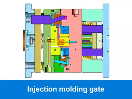
Injection Molding Gate
Injection molding gate is the core key connecting mold runner and cavity, which directly determines the plastic filling effect, part surface quality, dimensional stability and production efficiency. For mold designers and product engineers, mastering injection molding gate types, design rules and selection skills is essential to avoid common molding defects like flow marks, weld lines, sink marks and warpage. This article comprehensively explains the definition, classification, selection criteria, design key points, defect causes and improvement solutions of injection molding gates, helping you choose the optimal gate solution for different plastic products, materials and mass production demands.
1. What Is an Injection Molding Gate?
An injection molding gate is the small opening where molten plastic enters the mold cavity from the runner system. Acting as the critical connection between the runner and the cavity, the gate controls the flow rate, speed, and packing pressure of the plastic as it fills the part. Choosing the right gate type is essential, as it directly affects the part’s appearance, structural integrity, and manufacturing efficiency.
Although it is only a small area of the mold, the gate has a major impact on filling balance, packing pressure, surface quality, shrinkage, and part strength. Poor injection mold gate design can lead to flow marks, weld lines, sink marks, warpage, or visible gate marks.
Different products require different gate solutions, and the gate should be selected based on part structure, material flow, surface requirements, and production volume. For example, a thick-wall plastic part may need stronger and more direct filling, while a cosmetic housing may require better gate mark control and smoother flow behavior.
This is why gate selection should be reviewed together with the overall injection mold design, instead of being decided only after the mold structure is completed.
Therefore, injection molding gate design is not simply about creating a material entry point. It should be selected based on part structure, material properties, surface requirements, and mass production needs. A proper gate solution helps the part fill more consistently, reduces molding defects, and improves production efficiency.
“We can easily manage if we will only take, each day, the burden appointed to it. But the load will be too heavy for us if we carry yesterday’s burden over again today, and then add the burden of the morrow before we are required to bear it factorial non.”
Rebert Kosta
2. Injection Molding Gate Types
There is no single injection molding gate that works for every plastic part. The right type of gate in injection molding depends on part size, material, wall thickness, surface requirements, production volume, and mold structure. A good injection mold gate design should balance filling performance, gate mark control, production efficiency, and part quality.
Below are the most common injection molding gate types used in plastic mold design.
2.1 Sprue Gate
Sprue gate injection molding, also known as direct gate injection molding, allows molten plastic to flow directly from the sprue into the mold cavity. Because the flow path is short and the gate cross-section is relatively large, this type of gate in injection molding can provide strong filling pressure and reduce pressure loss during the filling stage.
In practical injection mold gate design, sprue gates are commonly used for large plastic parts, thick-wall components, and products with simple structures where appearance requirements are not the main priority. Compared with some other injection molding gate options, a sprue gate offers a more direct flow path, which can help materials with high viscosity or poor flowability enter the cavity more efficiently.
However, the gate and runner in injection molding must still be evaluated carefully. Since a sprue gate often leaves a larger gate mark and may create heat concentration near the gate area, it is usually not the first choice for high-gloss surfaces, transparent parts, or products with strict cosmetic requirements. For these applications, other solutions such as edge gates, tunnel gates, or valve gate injection molding may provide better control over gate marks and surface quality.

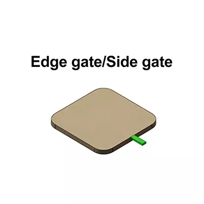
2.2 Edge Gate
An edge gate is one of the most common injection molding gate types. It is usually placed on the edge of the plastic part, allowing molten plastic to enter the mold cavity through the parting line. Because the structure is simple and easy to machine, it is widely used in standard injection mold gate design.
Compared with sprue gate injection molding, an edge gate offers more flexibility in gate location and is suitable for medium and large plastic parts, such as housings, covers, brackets, and structural components. However, the gate and runner in injection molding still need to be balanced carefully to avoid flow marks, weld lines, uneven shrinkage, or warpage.
Advantages of Edge Gate | Limitations of Edge Gate | Typical Applications |
Simple mold structure and cost-effective tooling. | Gate mark remains on the part edge and may require trimming. | Plastic housings, covers, brackets, panels. |
Suitable for medium and large parts with stable filling needs. | Poor gate location may cause flow marks or weld lines. | General industrial parts and electronic enclosures. |
Gate size and position are easy to adjust during mold design. | Not ideal for automatic degating or high cosmetic surfaces. | Automotive plastic parts and structural components. |
2.3 Tunnel Gate / Submarine Gate
A tunnel gate, also called a submarine gate, is an injection molding gate designed below the parting line. During ejection, the gate can be automatically separated from the part, making it suitable for high-volume production and projects that require less manual trimming.
In injection mold gate design, tunnel gates are often used for small and medium-sized plastic parts. Compared with sprue gate injection molding or edge gates, they provide better automation efficiency and help reduce secondary operations. However, the gate and runner in injection molding must be designed carefully, because improper tunnel gate size or angle may cause gate breakage, stress marks, or poor filling.
Advantages of Tunnel Gate | Limitations of Tunnel Gate | Typical Applications |
Allows automatic gate separation during ejection. | Not suitable for all materials, especially brittle plastics. | Small and medium plastic parts. |
Reduces manual trimming and improves production efficiency. | Gate angle and size must be carefully designed. | Caps, buttons, connectors, small housings. |
Helps keep the gate mark in a less visible area. | May cause stress or breakage if poorly designed. | High-volume injection molding projects. |

2.4 Pin Gate
A pin gate is commonly used in three-plate molds and multi-cavity molds. This injection molding gate creates a small gate mark and is often selected for precision plastic parts or products with higher appearance requirements.
In practical injection mold gate design, pin gates are useful when the gate needs to be placed in a specific location rather than on the part edge. They also support balanced filling in multi-cavity molds. However, compared with a simple edge gate, the mold structure is more complex, and tooling cost is usually higher.
Overall, a pin gate is a suitable type of gate in injection molding for small precision parts, especially when gate mark control and cavity balance are important.
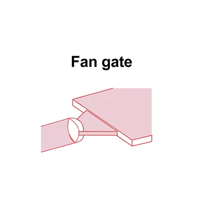
2.5 Fan Gate
A fan gate is an injection molding gate that gradually widens before entering the cavity. This wider gate area helps spread the melt flow more evenly, making it useful for thin-wall, flat, or wide plastic parts.
Compared with sprue gate injection molding, a fan gate does not focus the material flow in one small area. Instead, it distributes the flow across a wider section, which can help reduce flow marks, orientation stress, and warpage. However, because the gate area is larger, trimming is usually required after molding.
Advantages of Fan Gate | Limitations of Fan Gate | Typical Applications |
Improves melt flow distribution across wide areas. | Larger gate area usually requires trimming. | Thin-wall plastic parts. |
Helps reduce flow marks and material orientation effects. | Not ideal when a very small gate mark is required. | Flat covers, trays, panels, plates. |
Useful for parts that need smoother and more balanced filling. | Gate design must match part thickness and flow length. | Wide or shallow plastic products. |
2.6 Valve Gate
Valve gate injection molding is usually used in hot runner molds. The gate is opened and closed by a valve pin, allowing better control of melt flow, filling sequence, gate appearance, and production stability.
In high-volume projects, valve gates can reduce material waste, improve cosmetic quality, and support more precise filling control. This type of injection mold gate design is especially useful for large parts, appearance parts, multi-gate molds, and products where visible gate marks must be minimized. However, the system is more complex and requires higher mold design accuracy and maintenance.
Advantages of Valve Gate | Limitations of Valve Gate | Typical Applications |
Provides excellent control over gate opening and closing. | Higher mold cost than cold runner gate systems. | High-volume production molds. |
Helps reduce visible gate marks and improve surface quality. | Hot runner system is more complex. | Cosmetic plastic parts and large parts. |
Supports sequential filling and better flow control. | Requires precise mold design and regular maintenance. | Automotive parts, appliance housings, high-end enclosures. |
In practice, the gate and runner in injection molding must be designed together. Even if the gate type is correct, poor runner balance or wrong gate location can still cause flow marks, weld lines, shrinkage, or unstable dimensions. That is why gate selection should always be reviewed during DFM and Moldflow analysis before mold manufacturing begins.
3. Injection Molding Gate Selection: How to Choose the Right Gate
Choosing the right injection molding gate depends on part structure, material, appearance requirements, production volume, and mold cost. A good injection mold gate design should balance filling performance, gate mark control, production efficiency, and long-term molding stability.
Selection Factor | What to Consider | Recommended Gate Options |
Part size and wall thickness | Large or thick-wall parts need strong filling pressure, while thin-wall parts need fast and balanced flow. | Sprue gate injection molding, edge gate, fan gate |
Material flow behavior | PP and PE flow easily, while PC, PA+GF, PBT, and engineering plastics require more careful gate and runner design. | Edge gate, fan gate, hot runner gate, valve gate |
Surface appearance requirements | Cosmetic parts should avoid visible gate marks, flow marks, and weld lines on the main surface. | Tunnel gate, pin gate, valve gate injection molding |
Production volume | Low-volume projects may use simpler cold runner molds, while high-volume production often requires automatic gate removal or hot runner systems. | Edge gate, tunnel gate, hot runner gate, valve gate |
Gate removal method | Manual trimming increases labor cost. Automatic gate separation improves efficiency in mass production. | Tunnel gate, pin gate, hot runner gate |
Mold structure and cost | Simple gate structures reduce tooling cost, while advanced gate systems improve stability and appearance but increase mold cost. | Sprue gate, edge gate, pin gate, valve gate |
Part function and assembly | The gate should avoid sealing surfaces, assembly areas, clips, screw bosses, and load-bearing areas. | Depends on product design and Moldflow result |
4. Key Factors in Injection Molding Gate Design
A good injection molding gate is not only about choosing a gate type. Even if the right type of gate in injection molding is selected, poor gate location, improper gate size, or an unbalanced runner system can still cause defects in production. In practical injection mold gate design, the following three factors are especially important.
4.1 Gate Location and Part Function
Gate location directly affects how the plastic melt fills the cavity. A poor gate position can cause weld lines, air traps, flow marks, uneven shrinkage, or warpage.
For cosmetic parts, the gate should avoid visible surfaces. For functional parts, it should not be placed on sealing areas, clips, screw bosses, or critical assembly surfaces. In some cases, valve gate injection molding can help improve gate control and reduce visible gate marks on high-appearance parts.
4.2 Gate Size and Material Flow
Gate size affects filling pressure, packing efficiency, cooling time, and gate removal. If the gate is too small, the part may have short shots, weak weld lines, or poor packing. If the gate is too large, it may leave a visible gate mark and increase trimming work.
Material behavior also matters. PP and PE usually flow more easily, while PC, PBT, PA, POM, and glass-filled materials require more careful injection molding gate design. For example, sprue gate injection molding can provide strong filling for thick-wall parts, but it may leave a larger gate mark.
4.3 Gate and Runner Balance
The gate and runner in injection molding must be designed as one system. A balanced runner layout helps distribute pressure evenly, especially in multi-cavity molds. If the runner system is not balanced, some cavities may overfill while others are short, leading to unstable dimensions and inconsistent part quality.
That is why gate quantity, runner layout, and gate position should be reviewed together during DFM and Moldflow analysis. A well-balanced injection mold gate design helps reduce defects and supports stable mass production
5. Injection Molding Gate Defects
A poorly designed injection molding gate can cause many problems during molding, even when the mold structure and material selection seem correct. In many cases, defects are not caused by the plastic material itself, but by improper injection mold gate design, wrong gate location, or an unbalanced gate and runner in injection molding system.
Below are the most common defects related to injection molding gate design.
Gate Defect | Possible Cause | How to Improve |
Flow Marks | The melt flow is not smooth due to poor gate location, narrow gate size, or high injection speed near the gate area. | Optimize the injection molding gate position, adjust gate size, and improve flow balance with Moldflow analysis. |
Weld Lines | Melt fronts meet in weak or visible areas because the gate location is not properly selected. | Adjust gate position, add or reduce gate quantity, and review the gate and runner in injection molding layout. |
Sink Marks | The gate freezes too early, or packing pressure cannot reach thick-wall areas effectively. | Increase gate size if needed, improve packing pressure, or choose a better type of gate in injection molding for thick sections. |
Warpage | Unbalanced filling, uneven pressure, or poor runner balance causes uneven shrinkage after cooling. | Improve runner balance, optimize gate location, and review the full injection mold gate design before tooling. |
Visible Gate Marks | The gate is placed on a cosmetic surface or the gate type is not suitable for appearance parts. | Move the gate to a hidden area or consider valve gate injection molding for better gate control and cleaner appearance. |
Short Shot | The gate is too small, the flow path is too long, or the pressure loss is too high. | Increase gate size, shorten flow distance, or use sprue gate injection molding for large or thick-wall parts that need stronger filling. |
6. Conclusion
The injection molding gate may be small, but it has a major impact on plastic part quality and production stability. From selecting the right type of gate in injection molding to optimizing gate location, gate size, and the gate and runner in injection molding, every detail affects filling balance, surface appearance, shrinkage, warpage, and cycle efficiency. A well-planned injection mold gate design helps reduce molding defects and supports consistent mass production.
At PqMold, we review gate design during the early DFM stage and use Moldflow analysis to evaluate filling behavior, weld lines, air traps, and warpage risks before mold manufacturing begins. With strong experience in plastic injection mold manufacturing, precision CNC and EDM machining, and injection molding production, our engineering team can recommend suitable gate solutions, including edge gate, tunnel gate, pin gate, sprue gate injection molding, and valve gate injection molding for complex or high-appearance parts. Our goal is to help customers achieve stable production, better part quality, and reliable long-term molding performance.
FAQ
1. Why Does My Mold Work Well at T1 But Still Have Problems in Mass Production?
This often happens because the injection molding gate works under short trial conditions, but not under continuous production. Heat buildup, unstable packing, gate freeze time, and runner balance can change during long cycles. That is why gate design should be evaluated for real production, not only for T1 samples.
2. Can Changing the Gate Design Reduce My Production Cost?
Yes. A better injection mold gate design can reduce scrap, shorten cycle time, improve automatic degating, and lower trimming labor. For high-volume projects, the right gate solution can save much more than the initial mold cost difference.
3. Why Do My Plastic Parts Always have Visible Gate Marks?
Visible gate marks usually come from poor gate location, unsuitable gate type, or improper gate size. For cosmetic parts, the gate should be placed in a hidden area, or a cleaner solution such as hot runner or valve gate injection molding may be considered.
4. Is a Hot Runner or Valve Gate Always Better than a Cold Runner Gate?
Not always. Hot runner and valve gate systems can improve efficiency and surface quality, but they also increase mold cost and maintenance requirements. For simple or low-volume parts, a cold runner gate may be more cost-effective.
5. What Information Do You Need to Recommend the Right Gate Solution?
We usually need the 3D drawing, material, estimated production quantity, surface finish requirement, and any assembly or functional requirements. With this information, we can review the gate and runner in injection molding and recommend a suitable solution for stable production.

Injection Molding Defects: Flow Marks. Flow marks are surface defects on injection-molded plastic parts, manifesting as wavy lines, streaks, or discolored ring-like patterns, typically appearing around the gate area (as shown in the figure below). These defects can compromise the product’s appearance, aesthetics, localized structural strength, and functional reliability.
Root Causes:
The flow path or velocity of the melt is uneven, resulting in localized cooling or abnormal convergence.
How to prevent:
1. Adjust Injection Molding Process Parameters
Control injection speed, avoiding rates that are either too fast or too slow.
Increase melt temperature to reduce viscosity.
Increase mold temperature to slow down the cooling rate of the melt, facilitating smoother flow front convergence.
Appropriately extend the holding pressure time to ensure complete mold filling.
2. Optimize Mold Design
Adjust gate placement to minimize the impact of the melt against cold mold walls.
Improve runner design to reduce flow resistance.
Ensure uniform wall thickness throughout the part.
Strategically position the parting line to facilitate smooth melt convergence.
3. Material Selection
Utilize materials with superior flow properties.
Consider modifying filled materials to enhance the uniformity of their flow behavior.
3.Injection Molding Defects Commonly Caused by Material
9.Bubble/Void

In injection molding, a “gas pocket” refers to a void or gas-filled cavity formed within the interior or on the surface of a plastic part. Typically, this manifests on the part’s surface as a raised bump or a small pinhole; internally, a void may be present, and upon cross-sectioning the part, internal bubbles become visible—a phenomenon that is particularly pronounced in transparent or thin-walled components.
The root causes are:
Residual gas trapped within the mold cavity
Presence of moisture or volatile components in the material
Melt overheating or uneven cooling
Excessive injection speed or insufficient pressure
How to prevent
1. Venting and Mold Design
Enlarge vent channels or air vents: Ensure that air within the mold cavity can be expelled smoothly.
Ensure a smooth mold surface: Sharp corners or depressions tend to trap air; therefore, corners should be rounded or surfaces polished.
Ensure smooth gates and runners: Prevent the molten material from rapidly impacting and trapping air.
2. Injection Molding Process Optimization
Reduce excessive injection speed or pressure: Prevent the high-velocity flow of the molten material from trapping air within the cavity.
Increase holding pressure and duration: Compact the molten material to facilitate the expulsion of trapped gases.
Maintain uniform mold temperature: Prevent localized gas expansion that could lead to the formation of bubbles.
3. Material Handling
Dry plastic pellets: This is particularly critical for hygroscopic materials such as PA, PC, and ABS, to prevent moisture evaporation from causing bubbles.
Control melt temperature: Temperatures that are too high can generate volatile gases, while temperatures that are too low can result in uneven flow.
10.Discoloration

In injection molding, discoloration refers to the appearance of colors on the surface of a molded part that deviate from the specified color—such as yellowing, dark streaks, or black spots. This constitutes a surface defect. For products positioned as high-end or brand-name items, color inconsistency can make the product appear cheap or defective. In the case of mass-produced goods, significant color variations between individual units can compromise the visual uniformity of assembled sets or product series.
Root Causes:
The fundamental cause of discoloration is an abnormality in the material, temperature, or mold, resulting in an uneven color distribution within the melt or the occurrence of thermal or chemical changes.
How to prevent:
Our overall approach is as follows: maintain material cleanliness, ensure stable melt flow, and keep the mold clean with uniform temperature distribution. Specifically:
Material Preparation
Thoroughly dry raw materials: Especially hygroscopic materials such as PA, PC, and ABS.
Standardize raw material batches: Prevent color variations arising from different production batches.
Thoroughly mix masterbatch/colorants: Ensure uniform dispersion of coloring agents.
Process Optimization
Control barrel temperature: Avoid excessive heat that could lead to thermal degradation or scorching.
Control injection speed and holding pressure: Prevent localized uneven cooling of the melt or thermal shock against the cold mold wall, which can cause color variations.
Maintain uniform mold temperature: Ensure consistent cooling to minimize localized color differences.
Mold Management
Clean the mold cavity: Prevent contamination from scrap material or residues.
Polish or coat mold surfaces: Maintain the mold surface to prevent oxidation or fatigue from negatively impacting cooling efficiency.
4. Preventive Measures
In PqMold’s quality management system, the following preventive measures are particularly emphasized:
Mold Design Phase
Use CAE flow analysis to optimize the runner system, ensuring filling uniformity ≥95%
Cooling system layout must ensure temperature differences are controlled within ±5°C
Product structure DFM analysis to ensure moldability scores ≥85 points
Production Preparation Phase
Raw material inspection: 100% detection of key indicators such as moisture, melt flow index, and impurity content
Equipment maintenance: Precision inspection cycle for key components not exceeding 500 hours
Standard process documents: Include over 30 critical control points
Production Process Control
PqMold employs a digital production management system to achieve:
Real-time monitoring of process parameters, with deviations over ±3% triggering automatic alerts
Hourly sampling of product quality, establishing a quality tracking database
Response time for abnormal situations controlled within 15 minutes
5.Quality Control Key Points
Key Parameter Monitoring Standards:
Temperature: Material temperature fluctuation ±5°C, mold temperature fluctuation ±2°C
Pressure: Injection pressure fluctuation ±3%, holding pressure fluctuation ±2%
Time: Injection time fluctuation ±0.1 s, holding time fluctuation ±0.2 s, cooling time fluctuation ±1 s
Testing Methods and Standards:
Appearance inspection: Use standard light sources to ensure illumination of 800-1000 lux
Dimensional measurement: 100% detection of critical dimensions, general dimensions AQL 2.5 standard sampling
Performance testing: Execute mechanical, weather resistance, and other tests according to product requirements
By strictly implementing the above control measures, PqMold helps clients keep product defect rates below 0.1%, ensuring product quality remains at the industry’s leading level.
3. Conclusion
Injection molding typically entails significant upfront investment in tooling; therefore, designing and manufacturing the mold correctly the first time is critical to avoid the high costs associated with rework or remanufacturing. Defects related to the molding process or materials can often be resolved—at relatively low cost—by optimizing parameters, selecting appropriate materials, or implementing strict quality control measures. However, regardless of the underlying cause, defects in injection-molded products directly impact production efficiency, customer satisfaction, and profitability.
Implementing comprehensive quality control measures—including raw material inspection, in-process checks, mold debugging, and color control—can minimize defects. We utilize professional colorimeters to ensure color consistency across every batch of injection-molded parts, thereby preventing color variations that could compromise product aesthetics and brand image.
Now that you are familiar with common injection molding defects and their solutions, you can leverage robust quality control measures to ensure your products consistently meet both design specifications and your customers’ quality standards.